Have you ever wanted to test a 5-pin relay with a multimeter?
If you are planning on using a 5-Pin Relay or some other type of electrical component in your project, there will be times when you will need to test the relay with a multimeter. Although knowing how to test a relay manually is straightforward, this can be time-consuming and tedious. It may even take hours if the location of power sources is not easily accessible.
Many multimeter manufacturers are out in the market today, and they all price them differently depending on their quality and features. This article will help guide you on how to test a 5-pin relay with a multimeter, and the process can be less than 10 minutes; not only that, but it is also applicable to many other types of relays.
What is a 5-Pin Relay?
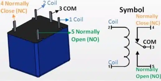
A 5-Pin relay is a 5-terminal electromechanical device that switches electrical currents using an electromagnetic actuator. The device has four terminals and a fifth terminal, the ground connection point. The four terminals are the supply, common, line, and neutral wires. The five-pin relay has an internal coil that acts as the switch that switches the two currents in your circuit.

Doing this test is simple; there are only four steps, and after you complete them, you will be able to test a 5-pin relay and display the result on your meter. A mechanical switch controls the relay’s movement, and once it receives power, it activates the electromagnetic coil that causes the switching action.
Tools and Equipment You’ll Need and Safety Precautions:
Invest in a good multimeter if you still need to get one. Also, make sure that your multimeter is relatively new and calibrated. If you are using an old multimeter, it may be out of calibration or unable to power the relay adequately.
- 5-pin relay
- Multimeter
- Jumper wires
- Power supply (e.g., 12V power source)
The multimeter’s terminals can become damaged if connected to a relay terminal with high voltage. You can prevent this from happening if you use an external power source to test the relay, but if you are using a battery for the test.
Make sure that you select a battery that has enough voltage to power your relay. Before testing your 5-pin relay, ensure that your multimeter is functioning properly and still in proper calibration. You can also use an ohmmeter while testing the relay, but this is only necessary if your multimeter cannot measure diodes.
It may be required that a rheostat or potentiometer be used when testing certain types of relays. Always attach your meter’s leads before connecting them to the 5-pin relay because there is no going back once you have connected them!
How to Test a 5-Pin Relay with a Multimeter

Preparing the Multimeter:
Make sure that your multimeter has a range of 0 to 20 VDC. If it does not, the relay’s coil may not function properly (or have reached its lifespan). Connecting your meter’s leads is a matter of personal preference; you can connect them in several ways: coaxially, using parallel wires, or directly. If you need help with this, any reputable electronics store should be able to guide you on connecting them to your relay.
If you decide that a different method would be better suited for your project. To prevent causing damage when testing the device, ensure the probes are insulated and grounded. If the leads are insulated, they will prevent any short-circuiting, but make sure that they are not too long, or else they may come in contact with other objects (like a screwdriver).
Testing the Coil Resistance
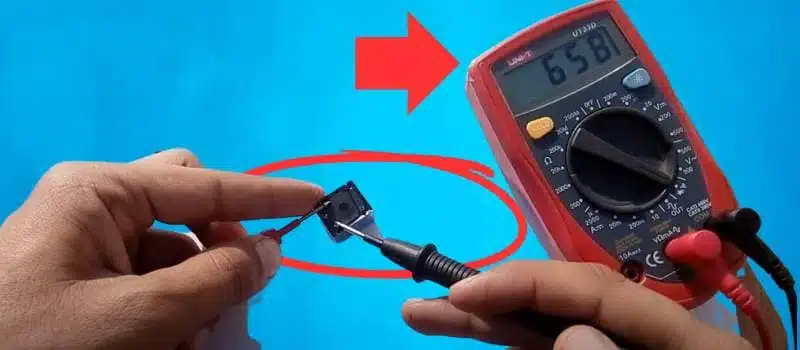
Coil resistance measures how much resistance an electric current needs to overcome for an electrical current to flow. It also specifies the “current carrying capacity” of a particular electromagnet, like the coil in your 5-pin relay. The value you measure should be the same as what was printed on the part you are testing, or it will not be accurate. For this test, connect one probe from your multimeter to either terminal on your relay and then connect the other probe to the ground.
The corresponding voltages will then appear on your meter’s display screen; if either value exceeds its range, you know your relay has a problem. One thing to remember when doing this test is that the relay may have a negative resistance (less than zero). If it has a value less than 100 Ω, the resistance across its coil should be greater than 100 Ω. You can solve this by using a 10 kΩ resistor.
Testing the Normally Open (NO) and Normally Closed (NC) Contacts
The normally open or normally closed contacts are terminals on your relay that make or break your circuit. In some cases, these terminals may be the same, but they are also used to contact different terminals on your relay.
The relay should have two terminals, which are named NO and NC. Using your multimeter, connect one probe to the NO terminal of the relay and another probe to the NC terminal. Now, you will start by measuring the resistance across these terminals. If both resistances are equal, you know that your relay is working properly; if they are different, then you know your device has a problem.
Testing the Switching Function
The relay’s switching function usually ranges between 0-1 Ohms (sometimes, there may be a multiplier to show this value). The relay has a coil and a magnet inside, which causes current to enter or exit, depending on how the switch is set. To test this function, you must measure the voltage across the contacts during step 2.
If you have any readings within that range, your relay works properly. If you do not have any such readings, your device has an issue. If none of these tests work out for you or if you are still not getting any results, you may need to consult an electrical engineer who can tell if your relay is defective or if there are some other problems, such as low battery voltage or a short circuit that occurred during testing.
Troubleshooting and Interpretation
If the noise comes from the relay, you may need to insulate the device or use a different battery. If the relay is connected to a series circuit, ensure that each device works properly and that there are no shorts in any part of the system. Make sure that the grounds are insulated from each other and do not touch together. If they do, you need to disconnect them; it may affect your results if they continue to touch during testing.
The coil should be attached to your 5-pin relay to work properly. If there are any defects on the part, make sure that you replace it. The NO and NC should not be connected because the circuit will not work properly if they are. If a short circuit occurs due to improper assembly, you will need to fix it before testing your device.
Practical Tips and Additional Information
When working with the relay, ensure your hands are protected. If you are not using insulated probes, your hands may become injured if the device experiences a short circuit. When working with a multimeter, ensure you avoid getting it near liquids of any kind; they can cause serious damage to your meter.
Sometimes if the meter is not completely dry, even when you think it should be, use some dry rice and put it in a bag; then shake it for several minutes. This will help ensure that there is no moisture on the insides of your device. If you are using a relay, ensure the device is grounded.
There should always be a ground somewhere in your circuit; you may have to ground it to the circuit board, or you may need to use a gasket underneath for it to work properly. Ensure that your relay has lug terminals connected to the circuit and can be accessed with a screwdriver.
Most of these lugs are accessible by scratching them off from the inside; this is especially important if used during installation. Many different kinds of relays exist, but most are operated by 5-pin operations, making them easier for engineers to operate and easier to identify and distinguish from other devices (such as switches).
Conclusion
I hope you will learn how to test a 5-Pin relay with a multimeter in this guide. When you order your relay, ensure you know how it operates. If you need to learn about the arrangement of the lugs, then you may be in trouble when trying to install them. Many different kinds of relays can be used, and they operate differently.
Many devices operate by using a series circuit instead of a parallel circuit, so if you use a relay to control them, ensure that both parts are working properly before you start your project.
Reference Resources:
- How Relays Work – Electronics Tutorials blog post explaining the basics of how relays work.
- How to Test a Relay – Mechanical Basics article provides a comprehensive guide to testing different types of relays.
- Relay Datasheets – Check the datasheets provided by relay manufacturers for specific technical details and testing instructions.
Related Articles
5 Best Fluke Multimeters for Automotive (2023 Buying Guide)
How to Test a Capacitor with a Multimeter [5 Easy Methods]
9 Best Multimeter for Automotive in any Budget (Reviewed)
What Does OL Mean on a Multimeter? (EXPLAINED)
Why are Fluke Multimeters So Expensive (Top 5 Reasons)
